FAQ
Most important questions and answers about Direct Current
The energy transition is a necessary component of the sustainable transformation of society. A manufacturer-independent direct current (DC) grid is a promising solution for the upcoming problems and challenges of industrial energy supply. To date, there are many myths about direct current that we would like to dispel here. In the following, we will distinguish between DC (direct current) and AC (alternating current).
1 Why should I use DC in my application?
DC is more efficient and uses fewer resources.
1. A DC grid allows for simple connection of solar panels and storage devices such as batteries and capacitors that inherently operate with DC.
2. Direct coupling via the DC grid allows for full use of braking energy – no need for braking resistors that dissipate heat.
3. Lower infeed power since the easily integrated storage devices can supply peak power. In the model application at project partner Mercedes-Benz this led to a reduction of peak in-feed power by 80%.
This means fewer ressources (transformer, current distribution) and reduced investment expense.
4. Higher availability: storage supplies enough energy for a controlled shutdown in case of power outages. When power is restored, one can simply resume production without the need to manually reset the devices or identifying and removing defective parts.
5. Many applications are already driven by devices such as frequency converters who in-ternally use a DC link. Connecting the DC links with each other makes the many AC-to-DC conversion steps redundant and allows for direct use of braking energy.
6. Easier off-grid operation enables uninterruptible power supply without extra effort, no additional components and reduced conversion losses.
7. Using DC less copper is needed for cabling – refer to question 4: For a 7.5 kW motor this means 50% less copper. In a DC grid the lo-cal AC-DC converters are redundant.
2 Which voltage is recommended for industrial applications?
We define two nominal voltages depending on the type of connection to the AC supply grid and a voltage band in which devices shall have full functionality:
1. For uncontrolled rectifiers on 400 V AC (typically B6 type) 540 V nominal voltage with a voltage band between 485 V and 750 V.
2. For uncontrolled rectifiers on 480 V AC and for controlled, bi-directional active infeed converters (AIC) the nominal voltage is 650 V with a voltage band between 600 V and 750 V.
3 What are voltage bands?
Voltage bands are predefined voltage ranges in which the components of a DC network provide different functionality. The IEC technical report 63282 has defined 7 bands. Each band Bx is defined by an upper voltage limit Ux. In the nominal band from 600 V to 750 V (for controlled infeed, AIC), the components operate continuously.
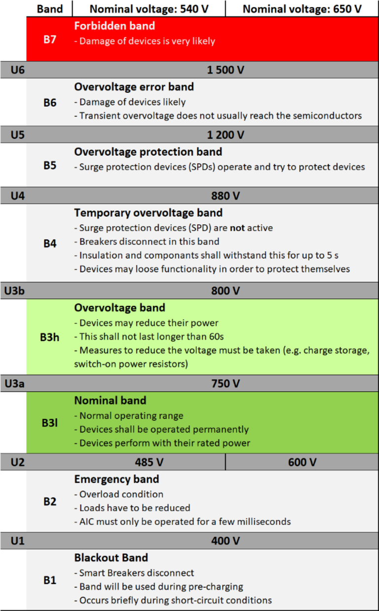
3.1 What is the Blackout band B1?
The applications do not work in this band below voltage U1 = 400 V. Therefore, except for pre-charging, the DC grid is only in this range for a short time (e.g. in the event of short circuits). When the voltage drops below U1, the Smart Breakers open.
3.2 What is the Emergency Band B2?
Voltages between 400 V and 485 V (for uncon-trolled rectifiers on 400 V AC) resp. between 400 V and 600 V (for AIC and for uncontrolled rectifiers on 480 V AC).
This band is characterized by a large overload. It is imperative that the load is reduced so that the DC grid does not change to band B1. Devices are allowed to reduce their power. Due to the DC voltage being too low, AICs may only be operated here for a few milliseconds.
3.3 What is the nominal band B3l?
- 600 V to 750 V (AIC or uncontrolled rectifiers on 480 V AC)
- 485 V to 750 V (uncontrolled rectifiers on 400 V AC)
This is the normal operating range of the DC grid. It is characterized by a power balance between local generation (e.g. from PV systems), feed-in from the AC grid and consumption of the loads. All equipment in the grid is designed to operate continuously in this range. Limitations of the device performance can result from physical boundary conditions, such as the state of charge of storage devices, the level of the mains voltage for supply devices, insufficient motor voltage or the solar irradiation for photo voltaic.
3.4 What is the overvoltage band B3h?
Voltages between 750 V and 800 V.
In this band, measures must be taken to prevent the shutdown threshold of the devices (800 V) from being reached. This can be done by feeding back into the AC grid, charging of energy storage devices but also switching-on power resistors. This state should not last longer than 60 s and devices may reduce their power in this state. This band is not yet included in TR 63282.
3.5 What is the temporary overvoltage band B4?
Voltages between 800 V and 880 V.
Overvoltage can occur due to switching operations, faults and braking of drives. A temporary overvoltage of up to 880 V for one minute is not problematic for common 400 V electrolytic capacitors (two in series). In the case of commonly used 1200 V semiconductors, however, the limit of voltage resistance may be reached by internal switching actions; such devices may lose their function in this range in order to protect themselves. Overvoltage protection devices (SPDs) do not yet limit the voltage in this band. If the voltage is in this range for a longer time (> 5 s) the upstream Smart Breaker opens to protect all devices.
3.6 What is the overvoltage protection band B5?
Voltages between 880 V and 1200 V.
In this area, the surge protection devices (SPDs) operate and try to protect devices from transient overvoltage caused by switching operations but also lightning strikes.
3.7 What is the overvoltage error band B6?
Voltages between 1200 V and 1500 V.
If the voltage is in this band, damage to the equipment is likely. Due to the damping properties of cables and input filters, short-term transient overvoltages do not usually cause damage to components in the devices.
3.8 What is the forbidden band B7?
Voltages higher than 1500 V.
In this voltage band, damage to the equipment (varistors, semiconductors, capacitors) is highly probable.
4 How much can I save on cabling using DC?
With the same insulation requirements and the same power, about 50% copper cross-section can be saved.
Example for a 7.5 kW three-phase motor connected with a frequency converter (cosφ=0.7,〖 η〗_Motor=0.887,η_Inverter=0.93):
AC:
400 V AC, 4 conductors (L1, L2, L3, PE)
Mains Current = 20 A (Lenze Manual for i550 Inverter) → this requires 2.5 mm² Cu-cross-section
4 × 2.5 mm² = 10 mm² Cu-cross-section
DC:
600 V, 3 conductors (Plus, Minus, PE)
15.2 A (P=U×I×η ) require 1.5 mm² Cu-cross-section
3 × 1.5 mm² = 4.5 mm² Cu-cross-section
55% less copper!
5 Are DC grids more dangerous than AC grids?
No, the same safety rules apply as for AC voltage. VDE 0100 and IEC 60364 allow up to 1000 V for AC and 1500 V for DC in low-voltage installations.
5.1 Where are the necessary protection measures for DC defined?
The basic safety standard IEC 61140 describes the protection measures up to DC 1500 V (and AC 1000 V). See here
5.2 What is an electrical arc?
An arc is a hot, conductive plasma, similar to a lightning bolt.
5.2.1 Which types of arcs are there?
There are two types of arcs:
- Deliberately generated arcs, e.g. during electric welding or when opening switching contacts.
- Fault arcs caused by a fault, e.g. cable break, insulation fault, foreign parts in switch cabinets.
5.2.2 Are there differences between AC- and DC arcs?
With DC, there are no current zero-crossings; therefore, additional measures must be imple-mented in the protective devices. In mechanical switches, these measures are, for example, magnetic fields and larger air gaps. Power electronics and hybrid switches are further options for preventing arcing in switchgear.
5.3 Can AC breakers be used for DC?
This cannot be answered in general – it depends on the specifications of the particular switch. Often AC switches are also approved for a certain DC voltage range according to the specific manufacturer's specifications and product standards.
6 Which grid types are there for DC?
There are basically the same grid types as for AC systems, i.e. TN, TT and IT systems.
In addition, there is the DC grid grounded on the AC side for industrial applications, since the systems are usually connected to the AC grid.
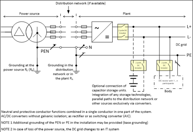
6.1 What does the AC-grounded DC-System look like?
The grounding reference is realized via the star point grounding at the transformer of the AC grid. The operational grounding takes place centrally at the transformer.
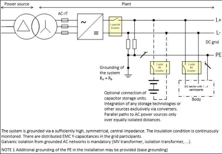
6.2 What does the DC IT grid look like?
In the DC IT grid variant, the DC grid is galvanically isolated from the AC grid via an isolating transformer. The reason for this is not, as with a classic IT grid, that the DC IT grid should continue to operate after an initial ground fault, but rather to simplify the parallel switching capability of power supply units.
In this DC IT grid, no further operation is permitted in the event of an earth fault; the fault location must be disconnected as quickly as possible by a circuit breaker (<10 s).
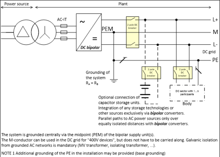
6.3 What does the mid-point earthed DC TN-S grid look like?
With this type of grounding, the midpoint of the DC voltage is earthed with low resistance. For this purpose, the supply unit can, for example, generate two DC voltages galvanically isolated from the AC mains, which are connected in series and whose midpoint is earthed with low resistance. In addition to the galvanic isolation, bipolar protection is required as with AC-side earthing.
6.4 What is the preferred grid type for DC?
Systems grounded on the AC side are recommended for systems installed in the vicinity of an AC hall (brownfield). IT systems are suitable for new installations as long as the insulation resistance is high (greenfield).
For extended installations with low insulation resistance, the center-point grounded DC-TN-S system is recommended.
The TT system with two different grounding points is not suitable because stray currents occur in the event of potential differences between the grounding points, which can lead to increased corrosion.
7 Which options do I have for changing an application from AC to DC?
1. Complete conversion from AC to DC
2. Modular conversion of individual plant sections to DC in an existing AC system
3. Use of devices that can be operated on AC as well as on DC
4. Expansion of applications in which DC systems already exist, e.g. for computer centres
7.1 What potential is offered by a complete change from AC to DC?
This is suitable for new plants and uses all the advantages of the DC systems such as energy efficiency and availability as described in question 1.
7.2 Where does a modular conversion of individual system components from AC to DC make sense?
This can be easily and quickly integrated into existing plants for replacement or expansion. The new or replaced plant section is connected to the AC system via an active infeed converter (AIC).
7.3 Where can devices that are compatible with both AC and DC be used?
Such devices are integrated in industrial DC grids as small consumers via suitable power supplies (DC/AC or DC/DC converters).
7.4 What must be taken into account when expanding DC systems?
The new and existing system can be coupled with each other, with different voltages via DC-DC converters. The voltage bands from question 3 should be taken into account here.